IMX95 VLS-GM2 Camera Usage Guide
Introduction
This article guides you how to get started using TechNexion VLS-GM2 GMSL2 camera modules on the EDM-IMX95 EVM board.
You must have the background knowledge to modify the kernel configuration, rebuild, and replace the kernel and the device tree source (DTS).
This article uses the IMX95-EVM baseboard as an example.
This article is based on the 🔗 Yocto 5.3 (Whinlatter) 2026Q2 Release.The corresponding Linux kernel version is 6.18.2-1.0.0.
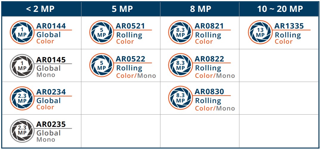
Supported Camera Modules
| Camera Series | Products |
|---|---|
| VLS-GM2 | VLS-GM2-AR0144 VLS-GM2-AR0145 VLS-GM2-AR0234 VLS-GM2-AR0235 VLS-GM2-AR0246 VLS-GM2-AR0521 VLS-GM2-AR0522 VLS-GM2-AR0544 VLS-GM2-AR0821 VLS-GM2-AR0822 VLS-GM2-AR0830 VLS-GM2-AR1335 VLS-GM2-AR2020 |
Supported Boards
| SoM | Board |
|---|---|
| EDM-IMX95 | IMX95-EVM |
This guide has been validated with eight VLS-GM2 cameras on TechNexion i.MX Release Distro 6.18-whinlatter, Linux kernel 6.18.2-g134dc8fa5253.
Example release check:
$ uname -r
6.18.2-g134dc8fa5253

$ cat /etc/os-release
ID=fsl-imx-xwayland
NAME="TechNexion i.MX Release Distro"
VERSION="6.18-whinlatter (whinlatter)"
VERSION_ID=6.18-whinlatter
VERSION_CODENAME="whinlatter"
PRETTY_NAME="TechNexion i.MX Release Distro 6.18-whinlatter (whinlatter)"
BUILD_ID="20260605052948"
Hardware Setup Instructions
1. Power Supply Preparation
- Use a DC 12V power cable to supply power to the board.
- The GMSL2 adapter board does not require a separate power input in this setup.
2. Debug Console Connection
- Prepare a USB-to-UART cable if you're connecting to a PC.
- Connect it to the UART_A_A55 connector.
3. Display Output Connection
- Prepare a 10.1 inch LVDS panel for output display.
- Connect the display to the LVDS connector on the board.
4. GMSL2 Adapter and Camera Connection
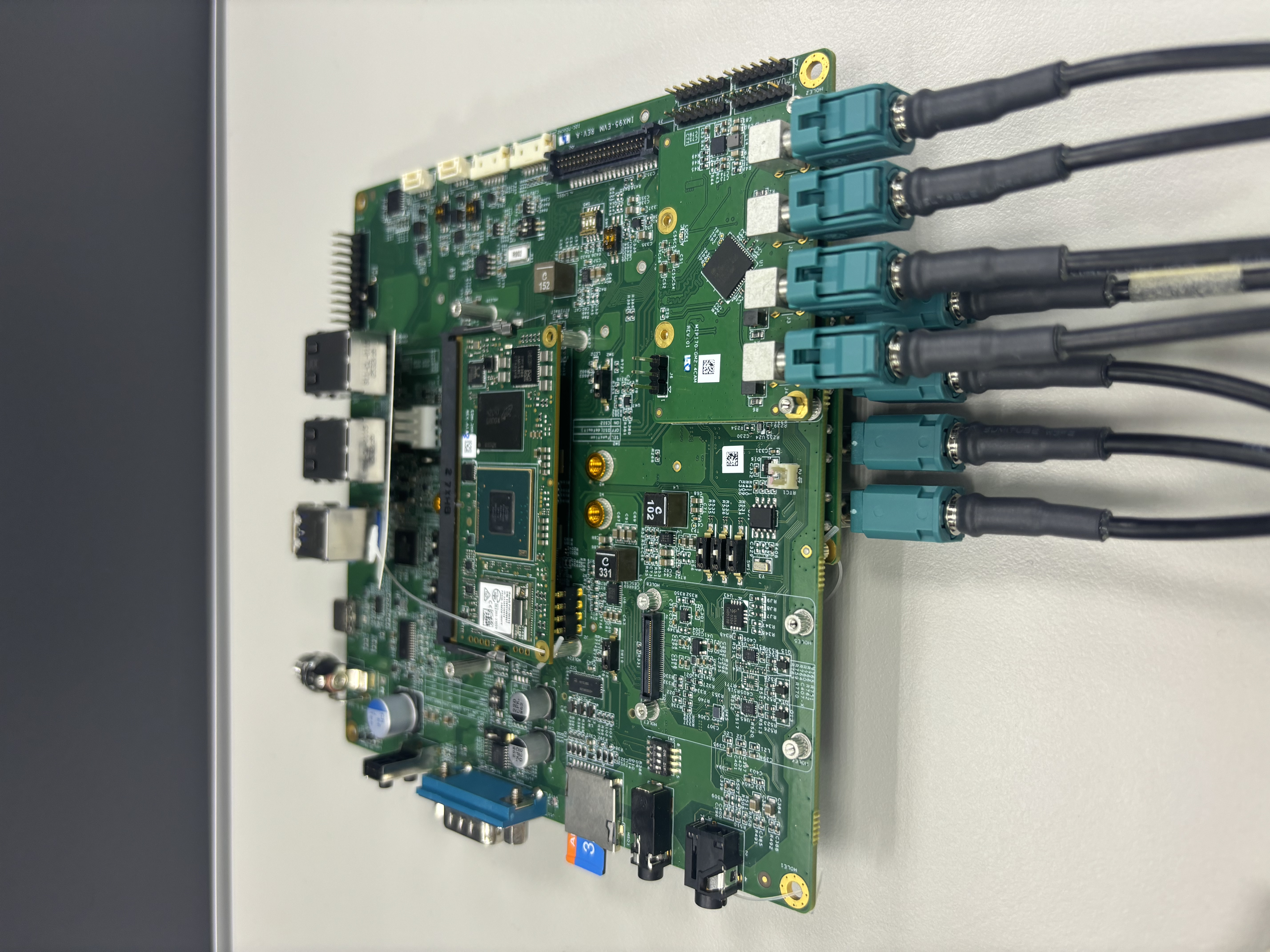
- Attach the GMSL2 adapter module directly to the IMX95-EVM board.
- No ribbon cable is required between the GMSL2 adapter module and the IMX95-EVM board.
- Connect the VLS-GM2 camera modules to the GMSL2 camera ports on the adapter module.
5. GMSL2 Camera Interface Overview
- VLS-GM2 cameras use a GMSL2 link between the camera serializer and the board-side deserializer.
- On i.MX95, the deserialized video stream is routed into the SoC through the CSI receivers and crossbar pipeline.
- Each CSI path can carry multiple virtual-channel camera streams when the board-side deserializer and device tree overlay are configured correctly.
If you are using the CSI2 connector, set the SW2 switch to the ON position to enable it.
6. Software Camera Path Mapping
The following mapping can be confirmed from cam -l, dmesg, and media-ctl -p. It follows the i.MX95 routing model described in i.MX95 Configuration.
| Camera | Device Tree Path | Deserializer | CSI Receiver | Pipeline | Board-Side Module |
|---|---|---|---|---|---|
| CAM1-CAM4 | /soc/bus@42000000/i2c@42540000/... | max96724 3-002e | csidev-4ad40000.csi | CSI2 / Pipeline B | CSI2 Module (Upper) |
| CAM5-CAM8 | /soc/bus@44000000/i2c@44350000/... | max96724 1-002e | csidev-4ad30000.csi | CSI1 / Pipeline A | CSI1 Module (Lower) |
Within each deserializer, the four GMSL2 links map to deserializer pads 0-3 in order. Use the CAM1-CAM8 names from this table when running the libcamerasrc display test.
Prepare Yocto Demo Image for Testing TechNexion Camera
To test TechNexion VLS-GM2 cameras, use a Yocto-based demo image that includes the required device tree overlays, GMSL2 deserializer/serializer drivers, and camera drivers.
Downloading the Demo Image
Prebuilt demo images are available for download on TechNexion's official server.
Download Link
Flashing the Image
You can flash the image to either e.MMC or an SD Card using one of the following methods.
1. Using uuu Tool (Universal Update Utility)
TechNexion provides a guide to flash the image using the uuu tool:
How to Flash with UUU
Before flashing, ensure the board is set to Serial Download Mode in the boot configuration.
2. Using ums Command in U-Boot (USB Mass Storage)
Alternatively, you can write the image directly to flash storage over USB-OTG using U-Boot's ums command:
Using UMS in U-Boot
The board must be booted with a version of U-Boot that supports the ums command. Typically, this is done from the existing e.MMC.
Build Yocto
TechNexion supports building a Yocto-based Linux image tailored for camera modules using the following kernel and branch.
Supported Linux Kernel
| Linux Kernel Version | Yocto Branch |
|---|---|
| 6.18.2 | tn-imx_6.18.2_1.0.0-stable |
Source and Build Instructions
📖 Build Yocto (Instructions for EDM-IMX95)
Confirm the kernel configuration symbols and device tree sources used by the VLS-GM2 overlays before adding board-specific patch instructions here.
Camera Testing Instructions
Specify Camera DTBO in U-Boot
-
Connect the debug console cable to the carrier board.
-
Power on the board and interrupt the boot process. Keep pressing
Enterwhen the following message appears:Hit any key to stop autoboot: -
Specify the appropriate device tree overlays for the LVDS panel and VLS-GM2 cameras using the
dtoverlayenvironment variable in U-Boot:
u-boot=> setenv dtoverlay lvds-vl10112880 vls-gm2-csi0 vls-gm2-csi1
The command above is an example for connecting cameras on both CSI paths simultaneously. If only one GMSL2 camera path is connected, use only the corresponding VLS-GM2 overlay, such as vls-gm2-csi0 or vls-gm2-csi1.
On the validated Yocto 5.3 Whinlatter image, fw_printenv dtoverlay may not be readable from Linux, and /proc/cmdline may not show the selected overlays. Use cam -l, media-ctl -p, and the streaming tests below to confirm that the VLS-GM2 camera paths are active.
- Continue the boot process.
u-boot=> saveenv
u-boot=> boot
Start Camera Video Stream via GStreamer
Launch GStreamer Pipeline
- List supported cameras:
$ cam -l
Available cameras:
1: 'tevs' (/base/soc/bus@42000000/i2c@42540000/max96724@2e/i2c-atr/i2c@0/serializer@40/i2c-atr/i2c@0/tevs@48)
2: 'tevs' (/base/soc/bus@42000000/i2c@42540000/max96724@2e/i2c-atr/i2c@1/serializer@40/i2c-atr/i2c@0/tevs@48)
3: 'tevs' (/base/soc/bus@42000000/i2c@42540000/max96724@2e/i2c-atr/i2c@2/serializer@40/i2c-atr/i2c@0/tevs@48)
4: 'tevs' (/base/soc/bus@42000000/i2c@42540000/max96724@2e/i2c-atr/i2c@3/serializer@40/i2c-atr/i2c@0/tevs@48)
5: 'tevs' (/base/soc/bus@44000000/i2c@44350000/max96724@2e/i2c-atr/i2c@0/serializer@40/i2c-atr/i2c@0/tevs@48)
6: 'tevs' (/base/soc/bus@44000000/i2c@44350000/max96724@2e/i2c-atr/i2c@1/serializer@40/i2c-atr/i2c@0/tevs@48)
7: 'tevs' (/base/soc/bus@44000000/i2c@44350000/max96724@2e/i2c-atr/i2c@2/serializer@40/i2c-atr/i2c@0/tevs@48)
8: 'tevs' (/base/soc/bus@44000000/i2c@44350000/max96724@2e/i2c-atr/i2c@3/serializer@40/i2c-atr/i2c@0/tevs@48)
This command displays available cameras and their names. In this eight-camera setup, cameras 1-4 are on the CSI2 path, and cameras 5-8 are on the CSI1 path.
Depending on the driver stack, VLS-GM2 camera endpoints may still appear as tevs sensors because the camera module behind the GMSL2 link uses a TEVS-compatible sensor interface.
- Check supported resolutions:
$ cam -c 1 --info
Using camera /base/soc/bus@42000000/i2c@42540000/max96724@2e/i2c-atr/i2c@0/serializer@40/i2c-atr/i2c@0/tevs@48 as cam0
0: 1280x800-YUYV/Rec709/sRGB/Rec601/Limited
 * Pixelformat: NV12 (1280x800)-(1280x800)/(+1,+1)
  - 1280x800
 * Pixelformat: ABGR8888 (1280x800)-(1280x800)/(+1,+1)
  - 1280x800
 * Pixelformat: BGR888 (1280x800)-(1280x800)/(+1,+1)
  - 1280x800
 * Pixelformat: RGB888 (1280x800)-(1280x800)/(+1,+1)
  - 1280x800
 * Pixelformat: XRGB8888 (1280x800)-(1280x800)/(+1,+1)
  - 1280x800
 * Pixelformat: YUV444 (1280x800)-(1280x800)/(+1,+1)
  - 1280x800
 * Pixelformat: RGB565 (1280x800)-(1280x800)/(+1,+1)
  - 1280x800
 * Pixelformat: NV16 (1280x800)-(1280x800)/(+1,+1)
  - 1280x800
 * Pixelformat: YUYV (1280x800)-(1280x800)/(+1,+1)
  - 1280x800
 * Pixelformat: AVUY8888 (1280x800)-(1280x800)/(+1,+1)
  - 1280x800
Replace 1 with the camera number from the previous step. This shows all supported pixel formats and resolutions.
- Launch GStreamer pipeline with
libcamerasrc:
$ gst-launch-1.0 libcamerasrc camera-name=$CAMERA_NAME ! \
  video/x-raw,format=YUY2,width=<res_w>,height=<res_h> ! \
  waylandsink sync=false
Replace $CAMERA_NAME with the actual camera name from step 1, and <res_w> and <res_h> with a resolution listed by cam -c <camera_index> --info, such as 1280x800.
YUY2 (YUYV) format is recommended for optimal performance and compatibility with most display sinks.
- Validate eight connected VLS-GM2 cameras with display output:
$ CAM1="/base/soc/bus@42000000/i2c@42540000/max96724@2e/i2c-atr/i2c@0/serializer@40/i2c-atr/i2c@0/tevs@48"
$ CAM2="/base/soc/bus@42000000/i2c@42540000/max96724@2e/i2c-atr/i2c@1/serializer@40/i2c-atr/i2c@0/tevs@48"
$ CAM3="/base/soc/bus@42000000/i2c@42540000/max96724@2e/i2c-atr/i2c@2/serializer@40/i2c-atr/i2c@0/tevs@48"
$ CAM4="/base/soc/bus@42000000/i2c@42540000/max96724@2e/i2c-atr/i2c@3/serializer@40/i2c-atr/i2c@0/tevs@48"
$ CAM5="/base/soc/bus@44000000/i2c@44350000/max96724@2e/i2c-atr/i2c@0/serializer@40/i2c-atr/i2c@0/tevs@48"
$ CAM6="/base/soc/bus@44000000/i2c@44350000/max96724@2e/i2c-atr/i2c@1/serializer@40/i2c-atr/i2c@0/tevs@48"
$ CAM7="/base/soc/bus@44000000/i2c@44350000/max96724@2e/i2c-atr/i2c@2/serializer@40/i2c-atr/i2c@0/tevs@48"
$ CAM8="/base/soc/bus@44000000/i2c@44350000/max96724@2e/i2c-atr/i2c@3/serializer@40/i2c-atr/i2c@0/tevs@48"
$
$ for CAM in "$CAM1" "$CAM2" "$CAM3" "$CAM4" "$CAM5" "$CAM6" "$CAM7" "$CAM8"; do
>   echo "Testing $CAM"
>   timeout 10 gst-launch-1.0 libcamerasrc camera-name="$CAM" ! \
>     video/x-raw,format=YUY2,width=1280,height=800 ! \
>     waylandsink sync=false
> done
Example successful output:
Testing /base/soc/bus@42000000/i2c@42540000/max96724@2e/i2c-atr/i2c@0/serializer@40/i2c-atr/i2c@0/tevs@48
Setting pipeline to PAUSED ...
Pipeline is live and does not need PREROLL ...
Pipeline is PREROLLED ...
Setting pipeline to PLAYING ...
New clock: GstSystemClock
Redistribute latency...
Testing /base/soc/bus@42000000/i2c@42540000/max96724@2e/i2c-atr/i2c@1/serializer@40/i2c-atr/i2c@0/tevs@48
Setting pipeline to PAUSED ...
Pipeline is live and does not need PREROLL ...
Pipeline is PREROLLED ...
Setting pipeline to PLAYING ...
New clock: GstSystemClock
Redistribute latency...
Testing /base/soc/bus@42000000/i2c@42540000/max96724@2e/i2c-atr/i2c@2/serializer@40/i2c-atr/i2c@0/tevs@48
Setting pipeline to PAUSED ...
Pipeline is live and does not need PREROLL ...
Pipeline is PREROLLED ...
Setting pipeline to PLAYING ...
New clock: GstSystemClock
Redistribute latency...
Testing /base/soc/bus@42000000/i2c@42540000/max96724@2e/i2c-atr/i2c@3/serializer@40/i2c-atr/i2c@0/tevs@48
Setting pipeline to PAUSED ...
Pipeline is live and does not need PREROLL ...
Pipeline is PREROLLED ...
Setting pipeline to PLAYING ...
New clock: GstSystemClock
Redistribute latency...
Testing /base/soc/bus@44000000/i2c@44350000/max96724@2e/i2c-atr/i2c@0/serializer@40/i2c-atr/i2c@0/tevs@48
Setting pipeline to PAUSED ...
Pipeline is live and does not need PREROLL ...
Pipeline is PREROLLED ...
Setting pipeline to PLAYING ...
New clock: GstSystemClock
Redistribute latency...
Testing /base/soc/bus@44000000/i2c@44350000/max96724@2e/i2c-atr/i2c@1/serializer@40/i2c-atr/i2c@0/tevs@48
Setting pipeline to PAUSED ...
Pipeline is live and does not need PREROLL ...
Pipeline is PREROLLED ...
Setting pipeline to PLAYING ...
New clock: GstSystemClock
Redistribute latency...
Testing /base/soc/bus@44000000/i2c@44350000/max96724@2e/i2c-atr/i2c@2/serializer@40/i2c-atr/i2c@0/tevs@48
Setting pipeline to PAUSED ...
Pipeline is live and does not need PREROLL ...
Pipeline is PREROLLED ...
Setting pipeline to PLAYING ...
New clock: GstSystemClock
Redistribute latency...
Testing /base/soc/bus@44000000/i2c@44350000/max96724@2e/i2c-atr/i2c@3/serializer@40/i2c-atr/i2c@0/tevs@48
Setting pipeline to PAUSED ...
Pipeline is live and does not need PREROLL ...
Pipeline is PREROLLED ...
Setting pipeline to PLAYING ...
New clock: GstSystemClock
Redistribute latency...
This eight-camera test has been validated at 1280x800 with YUY2. The test is considered successful when each camera pipeline reaches PLAYING, no GStreamer error is reported, and the display shows the corresponding camera stream before timeout stops the pipeline.
If GStreamer reports streaming stopped, reason not-negotiated (-4), check cam -c <camera_index> --info and make sure the requested width, height, and pixel format are listed.
Check Media Controller
Use media-ctl to inspect the active media graph after running cam -l or starting a libcamerasrc stream.
$ media-ctl -p
Example output, abridged to the camera-route related sections. The repeated mxc_isi.* capture node details are omitted because they only show the eight ISI output paths after the crossbar.
Media controller API version 6.18.2

Media device information
------------------------
driver          mxc-isi
model           FSL Capture Media Device
bus info        platform:4ad50000.isi
driver version  6.18.2

Device topology
- entity 1: crossbar (13 pads, 11 links, 8 routes)
            type V4L2 subdev subtype Unknown flags 0
            device node name /dev/v4l-subdev0
        routes:
                3/0 -> 5/0 [ACTIVE]
                3/1 -> 6/0 [ACTIVE]
                3/2 -> 7/0 [ACTIVE]
                3/3 -> 8/0 [ACTIVE]
                2/0 -> 9/0 [ACTIVE]
                2/1 -> 10/0 [ACTIVE]
                2/2 -> 11/0 [ACTIVE]
                2/3 -> 12/0 [ACTIVE]

... mxc_isi.0 through mxc_isi.7 capture node sections omitted ...

- entity 110: 4ac10000.syscon:formatter@20 (2 pads, 2 links, 4 routes)
              device node name /dev/v4l-subdev9
        routes:
                0/0 -> 1/0 [ACTIVE]
                0/1 -> 1/1 [ACTIVE]
                0/2 -> 1/2 [ACTIVE]
                0/3 -> 1/3 [ACTIVE]
        pad0: SINK
                <- "csidev-4ad30000.csi":1 [ENABLED,IMMUTABLE]
        pad1: SOURCE
                -> "crossbar":2 [ENABLED,IMMUTABLE]

- entity 115: csidev-4ad30000.csi (2 pads, 2 links, 4 routes)
              device node name /dev/v4l-subdev10
        routes:
                0/0 -> 1/0 [ACTIVE]
                0/1 -> 1/1 [ACTIVE]
                0/2 -> 1/2 [ACTIVE]
                0/3 -> 1/3 [ACTIVE]
        pad0: SINK
                <- "max96724 1-002e":4 [ENABLED]
        pad1: SOURCE
                -> "4ac10000.syscon:formatter@20":0 [ENABLED,IMMUTABLE]

- entity 120: 4ac10000.syscon:formatter@120 (2 pads, 2 links, 4 routes)
              device node name /dev/v4l-subdev11
        routes:
                0/0 -> 1/0 [ACTIVE]
                0/1 -> 1/1 [ACTIVE]
                0/2 -> 1/2 [ACTIVE]
                0/3 -> 1/3 [ACTIVE]
        pad0: SINK
                <- "csidev-4ad40000.csi":1 [ENABLED,IMMUTABLE]
        pad1: SOURCE
                -> "crossbar":3 [ENABLED,IMMUTABLE]

- entity 125: csidev-4ad40000.csi (2 pads, 2 links, 4 routes)
              device node name /dev/v4l-subdev12
        routes:
                0/0 -> 1/0 [ACTIVE]
                0/1 -> 1/1 [ACTIVE]
                0/2 -> 1/2 [ACTIVE]
                0/3 -> 1/3 [ACTIVE]
        pad0: SINK
                <- "max96724 3-002e":4 [ENABLED]
        pad1: SOURCE
                -> "4ac10000.syscon:formatter@120":0 [ENABLED,IMMUTABLE]

- entity 130: max96724 3-002e (9 pads, 5 links, 4 routes)
              device node name /dev/v4l-subdev13
        routes:
                0/0 -> 4/0 [ACTIVE]
                1/0 -> 4/1 [ACTIVE]
                2/0 -> 4/2 [ACTIVE]
                3/0 -> 4/3 [ACTIVE]
        pad0: SINK
                <- "max96717 8-0040":1 [ENABLED,IMMUTABLE]
        pad1: SINK
                <- "max96717 9-0040":1 [ENABLED,IMMUTABLE]
        pad2: SINK
                <- "max96717 10-0040":1 [ENABLED,IMMUTABLE]
        pad3: SINK
                <- "max96717 11-0040":1 [ENABLED,IMMUTABLE]
        pad4: SOURCE
                -> "csidev-4ad40000.csi":0 [ENABLED]

- entity 142: max96724 1-002e (9 pads, 5 links, 4 routes)
              device node name /dev/v4l-subdev14
        routes:
                0/0 -> 4/0 [ACTIVE]
                1/0 -> 4/1 [ACTIVE]
                2/0 -> 4/2 [ACTIVE]
                3/0 -> 4/3 [ACTIVE]
        pad0: SINK
                <- "max96717 12-0040":1 [ENABLED,IMMUTABLE]
        pad1: SINK
                <- "max96717 13-0040":1 [ENABLED,IMMUTABLE]
        pad2: SINK
                <- "max96717 14-0040":1 [ENABLED,IMMUTABLE]
        pad3: SINK
                <- "max96717 15-0040":1 [ENABLED,IMMUTABLE]
        pad4: SOURCE
                -> "csidev-4ad30000.csi":0 [ENABLED]

- entity 154: max96717 8-0040 (3 pads, 2 links, 1 route)
        pad0: SINK
                <- "tevs 16-0048":0 [ENABLED,IMMUTABLE]
        pad1: SOURCE
                -> "max96724 3-002e":0 [ENABLED,IMMUTABLE]

- entity 160: max96717 9-0040 (3 pads, 2 links, 1 route)
        pad0: SINK
                <- "tevs 17-0048":0 [ENABLED,IMMUTABLE]
        pad1: SOURCE
                -> "max96724 3-002e":1 [ENABLED,IMMUTABLE]

- entity 166: max96717 10-0040 (3 pads, 2 links, 1 route)
        pad0: SINK
                <- "tevs 18-0048":0 [ENABLED,IMMUTABLE]
        pad1: SOURCE
                -> "max96724 3-002e":2 [ENABLED,IMMUTABLE]

- entity 172: max96717 11-0040 (3 pads, 2 links, 1 route)
        pad0: SINK
                <- "tevs 19-0048":0 [ENABLED,IMMUTABLE]
        pad1: SOURCE
                -> "max96724 3-002e":3 [ENABLED,IMMUTABLE]

- entity 178: max96717 12-0040 (3 pads, 2 links, 1 route)
        pad0: SINK
                <- "tevs 20-0048":0 [ENABLED,IMMUTABLE]
        pad1: SOURCE
                -> "max96724 1-002e":0 [ENABLED,IMMUTABLE]

- entity 184: max96717 13-0040 (3 pads, 2 links, 1 route)
        pad0: SINK
                <- "tevs 21-0048":0 [ENABLED,IMMUTABLE]
        pad1: SOURCE
                -> "max96724 1-002e":1 [ENABLED,IMMUTABLE]

- entity 190: max96717 14-0040 (3 pads, 2 links, 1 route)
        pad0: SINK
                <- "tevs 22-0048":0 [ENABLED,IMMUTABLE]
        pad1: SOURCE
                -> "max96724 1-002e":2 [ENABLED,IMMUTABLE]

- entity 196: max96717 15-0040 (3 pads, 2 links, 1 route)
        pad0: SINK
                <- "tevs 23-0048":0 [ENABLED,IMMUTABLE]
        pad1: SOURCE
                -> "max96724 1-002e":3 [ENABLED,IMMUTABLE]

- entity 202: tevs 16-0048 (1 pad, 1 link, 0 routes)
        pad0: SOURCE
                [stream:0 fmt:UYVY8_1X16/1280x800@1/60 field:none colorspace:srgb]
                -> "max96717 8-0040":0 [ENABLED,IMMUTABLE]

... tevs 17-0048 through tevs 22-0048 sections omitted ...

- entity 230: tevs 23-0048 (1 pad, 1 link, 0 routes)
        pad0: SOURCE
                [stream:0 fmt:UYVY8_1X16/1280x800@1/60 field:none colorspace:srgb]
                -> "max96717 15-0040":0 [ENABLED,IMMUTABLE]
For i.MX95 GMSL2 routing details, see i.MX95 Configuration.
With the current libcamera stack, camera media routes are configured automatically when libcamerasrc starts the camera pipeline. Manual media-ctl route activation is not required for the validated eight-camera GMSL2 setup.
For an eight-camera setup, media-ctl -p should show two max96724 deserializers, eight max96717 serializers, and eight TEVS-compatible camera endpoints behind the GMSL2 links. max96724 1-002e should connect to csidev-4ad30000.csi and max96724 3-002e should connect to csidev-4ad40000.csi.
Troubleshooting
Verify Camera and GMSL2 Initialization
Use dmesg to check whether the GMSL2 deserializer/serializer and camera sensor drivers initialized correctly. grep tevs is enough to check the camera sensor probe logs only, but the broader filter below is recommended for VLS-GM2 because it also catches the GMSL2 deserializer, serializer, CSI, and camera framework messages.
$ dmesg | grep -Ei "max967|vls|tevs|csi|camera"
If the dmesg ring buffer no longer contains the boot-time probe logs, use journalctl when it is available:
$ journalctl -k -b | grep -Ei "max967|vls|tevs|csi|camera"
If both commands return no boot-time probe messages, use cam -l, media-ctl -p, and the GStreamer streaming test as the current-state checks.
Example output, abridged to the routing and probe lines:
[    0.513812] /soc/bus@42000000/i2c@42540000/max96724@2e: Fixed dependency cycle(s) with /soc/csi@4ad40000
[    0.782560] /soc/bus@44000000/i2c@44350000/max96724@2e: Fixed dependency cycle(s) with /soc/csi@4ad30000
[    1.014460] /soc/syscon@4ac10000/formatter@20: Fixed dependency cycle(s) with /soc/csi@4ad30000
[    1.031879] /soc/syscon@4ac10000/formatter@120: Fixed dependency cycle(s) with /soc/csi@4ad40000
[    1.040686] /soc/csi@4ad30000: Fixed dependency cycle(s) with /soc/syscon@4ac10000/formatter@20
[    1.049296] /soc/csi@4ad30000: Fixed dependency cycle(s) with /soc/bus@44000000/i2c@44350000/max96724@2e
[    1.058768] /soc/csi@4ad40000: Fixed dependency cycle(s) with /soc/syscon@4ac10000/formatter@120
[    1.067492] /soc/csi@4ad40000: Fixed dependency cycle(s) with /soc/bus@42000000/i2c@42540000/max96724@2e
...
[   14.836444] tevs 16-0048: tevs_probe() device node: tevs@48
[   15.357471] tevs 16-0048: Version:26.1.0.1
[   15.363144] tevs 16-0048: Product:TEVS-AR0144, HeaderVer:3, MIPI_Rate:560
[   15.363428] tevs 16-0048: Chip ID: 0x0356
[   15.387848] tevs 16-0048: probe success
[   15.388358] tevs 17-0048: tevs_probe() device node: tevs@48
[   15.905447] tevs 17-0048: Version:25.10.0.1
[   15.910258] tevs 17-0048: Product:TEVS-AR0144, HeaderVer:3, MIPI_Rate:560
[   15.910558] tevs 17-0048: Chip ID: 0x0356
[   15.944856] tevs 17-0048: probe success
[   15.945284] tevs 18-0048: tevs_probe() device node: tevs@48
[   16.477688] tevs 18-0048: Version:25.12.0.1
[   16.482589] tevs 18-0048: Product:TEVS-AR0144, HeaderVer:3, MIPI_Rate:560
[   16.482911] tevs 18-0048: Chip ID: 0x0356
[   16.517708] tevs 18-0048: probe success
[   16.518451] tevs 19-0048: tevs_probe() device node: tevs@48
[   17.053844] tevs 19-0048: Version:25.12.0.1
[   17.058849] tevs 19-0048: Product:TEVS-AR0144, HeaderVer:3, MIPI_Rate:560
[   17.059171] tevs 19-0048: Chip ID: 0x0356
[   17.083654] tevs 19-0048: probe success
[   17.084155] tevs 20-0048: tevs_probe() device node: tevs@48
[   17.597906] tevs 20-0048: Version:25.10.0.1
[   17.602887] tevs 20-0048: Product:TEVS-AR0144, HeaderVer:3, MIPI_Rate:560
[   17.603211] tevs 20-0048: Chip ID: 0x0356
[   17.638092] tevs 20-0048: probe success
[   17.638840] tevs 21-0048: tevs_probe() device node: tevs@48
[   18.173595] tevs 21-0048: Version:25.12.0.1
[   18.178676] tevs 21-0048: Product:TEVS-AR0144, HeaderVer:3, MIPI_Rate:560
[   18.179003] tevs 21-0048: Chip ID: 0x0356
[   18.214011] tevs 21-0048: probe success
[   18.214994] tevs 22-0048: tevs_probe() device node: tevs@48
[   18.781917] tevs 22-0048: Version:25.12.0.1
[   18.786994] tevs 22-0048: Product:TEVS-AR0144, HeaderVer:3, MIPI_Rate:560
[   18.787323] tevs 22-0048: Chip ID: 0x0356
[   18.822872] tevs 22-0048: probe success
[   18.823618] tevs 23-0048: tevs_probe() device node: tevs@48
[   19.357843] tevs 23-0048: Version:25.10.0.1
[   19.362831] tevs 23-0048: Product:TEVS-AR0144, HeaderVer:3, MIPI_Rate:560
[   19.363158] tevs 23-0048: Chip ID: 0x0356
[   19.417074] tevs 23-0048: probe success
The Fixed dependency cycle(s) lines are expected graph dependency messages on this platform. They are useful for confirming the CSI/deserializer mapping, but they are not probe failures. The important sensor confirmation is that tevs 16-0048 through tevs 23-0048 all report probe success.
Check Available Devices
Verify that the video and media devices are available.
$ v4l2-ctl --list-device
Example output:
mxc-isi-cap (platform:4ad50000.isi):
        /dev/video0
        /dev/video1
        /dev/video2
        /dev/video3
        /dev/video4
        /dev/video5
        /dev/video6
        /dev/video7
        /dev/video8
        /dev/media0

mxc-jpeg codec (platform:4c500000.jpegdec):
        /dev/video11

mxc-jpeg codec (platform:4c550000.jpegenc):
        /dev/video12

wave6-dec (platform:wave6-dec):
        /dev/video9

wave6-enc (platform:wave6-enc):
        /dev/video10
Ensure that /dev/media0 is present in the device list. This media controller device is essential for configuring the camera pipeline and managing the video capture interfaces.
Check GMSL2 Link Quality
If the camera probes but streaming is unstable, run a GMSL2 link margin test. See GMSL Link Margin Testing.
GStreamer Reports not-negotiated
If gst-launch-1.0 reports streaming stopped, reason not-negotiated (-4), the requested caps do not match the formats exposed by libcamera or accepted by the display sink.
$ cam -c 1 --info
Use a listed mode in the GStreamer caps. On the validated Yocto 5.3 Whinlatter image, VLS-GM2 cameras expose 1280x800 through libcamera, so 1280x720 may fail unless that mode is listed for the selected camera.