i.MX95 Configuration
i.MX95 Configuration
The i.MX95 platform is a powerhouse for vision applications but requires careful configuration due to its Crossbar routing architecture. Unlike simpler chips, the i.MX95 uses a chain of intermediate devices (csidev, formatter, crossbar) to route data to the ISP.
Visualizing the Architecture
The i.MX95 routing topology is complex. Data flows through several blocks before reaching the processing pipeline.
GMSL YAML Configurator & Exporter
Use the interactive configurator below to start from a predefined Hardware Preset, or manually enable CSI modules and toggle individual ports. The YAML output updates in real-time and can be copied directly into your media_link.yaml file.
Enable a CSI module only if the corresponding CSI connector is physically attached to the board.
If a connector is unplugged or absent, leave the module disabled. Enabling a module whose connector is not present will cause the route to fail.
| Configuration | Connection | Active Ports | Action |
|---|---|---|---|
2 cameras on CSI1 VxRoute_iMX95_GMSL_2CAM_CSI1.yaml | 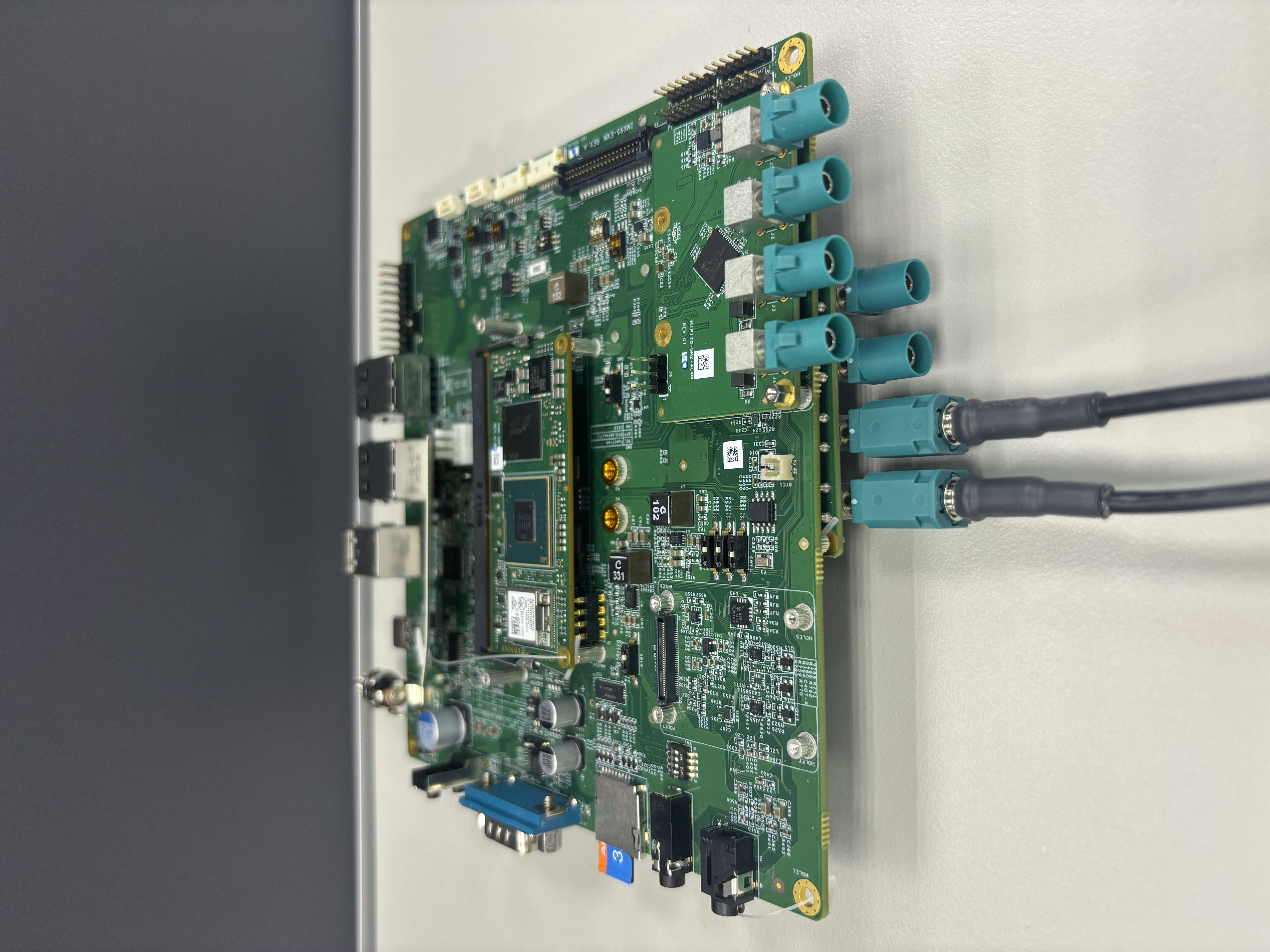 | CSI2 P3P2P1P0 CSI1 P0P1P2P3 | |
2 cameras on CSI1 ONLY VxRoute_iMX95_GMSL_2CAM_CSI1_ONLY.yaml | 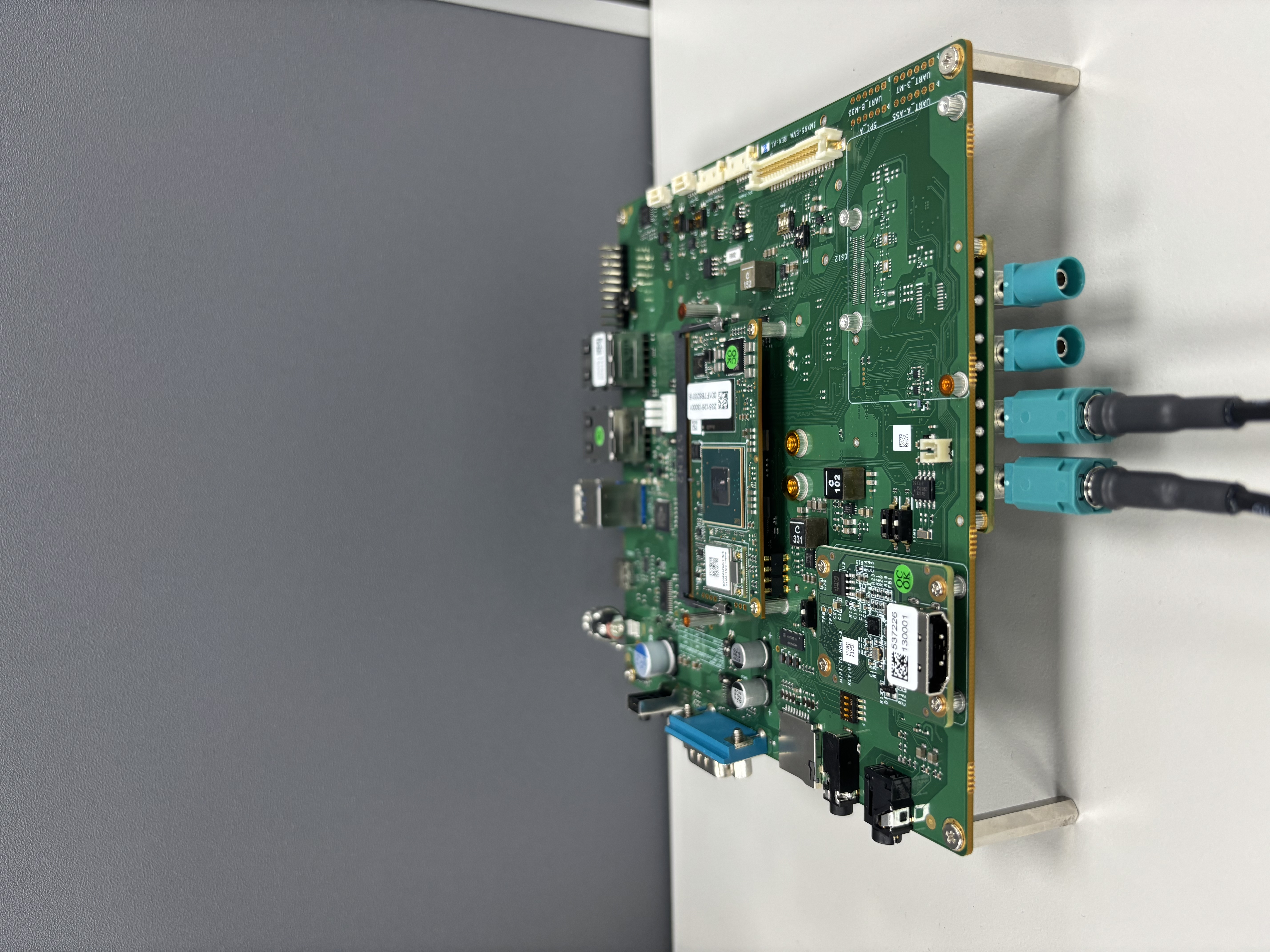 | CSI1 P0P1P2P3 | |
4 cameras on CSI1 VxRoute_iMX95_GMSL_CSI1.yaml | 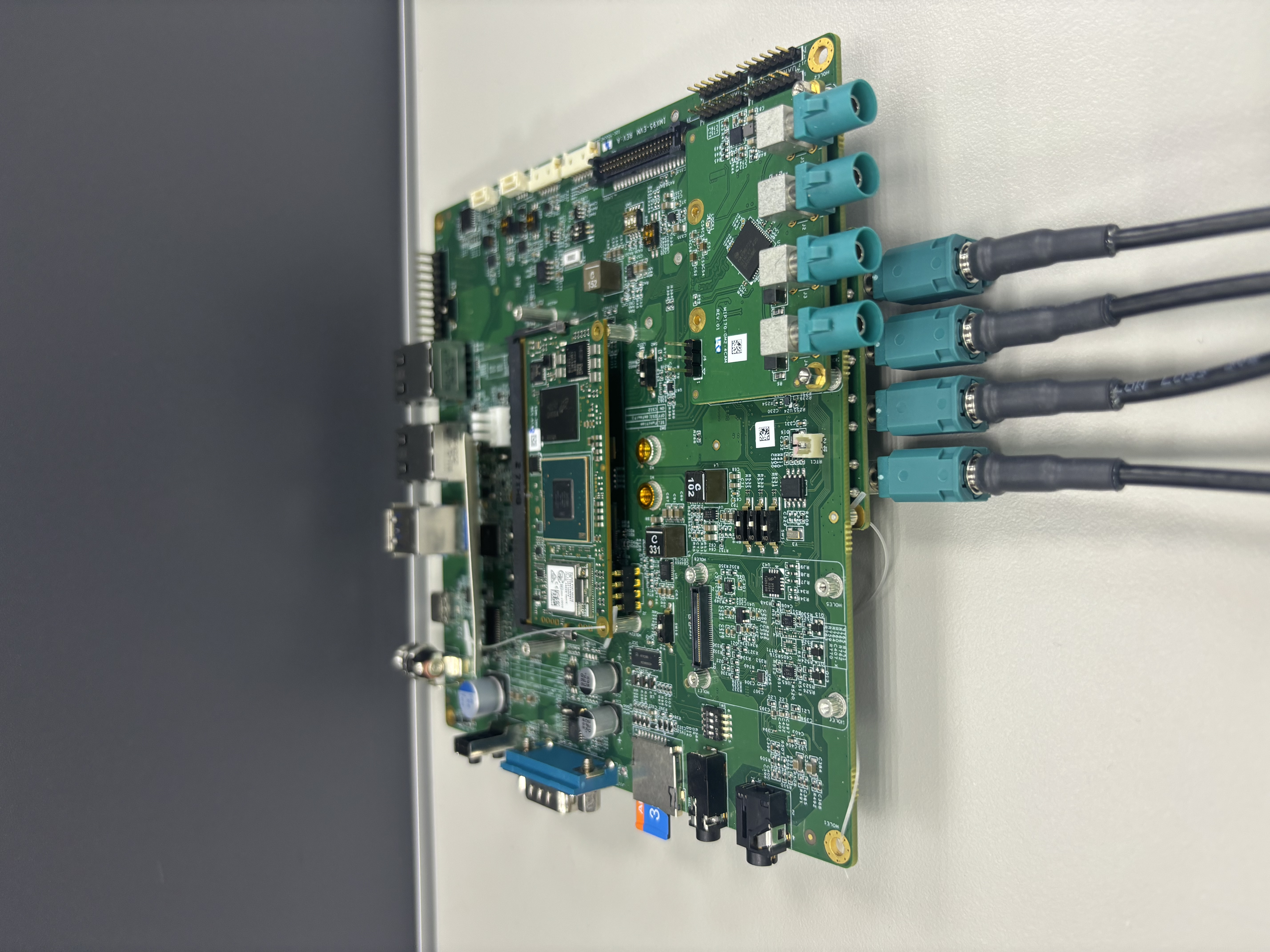 | CSI2 P3P2P1P0 CSI1 P0P1P2P3 | |
4 cameras on CSI1 ONLY VxRoute_iMX95_GMSL_CSI1_ONLY.yaml | 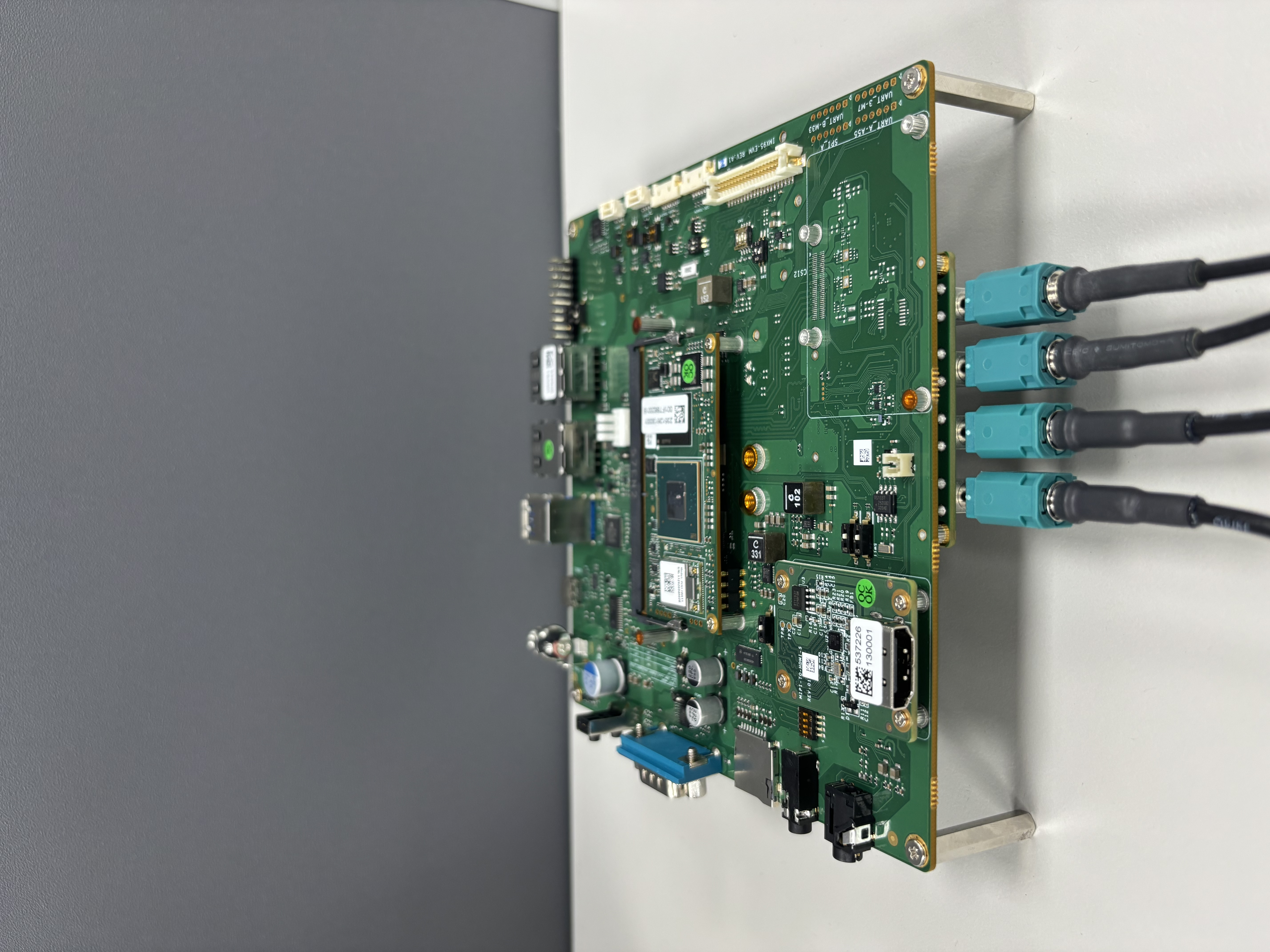 | CSI1 P0P1P2P3 | |
4 cameras on CSI2 VxRoute_iMX95_GMSL_CSI2.yaml | 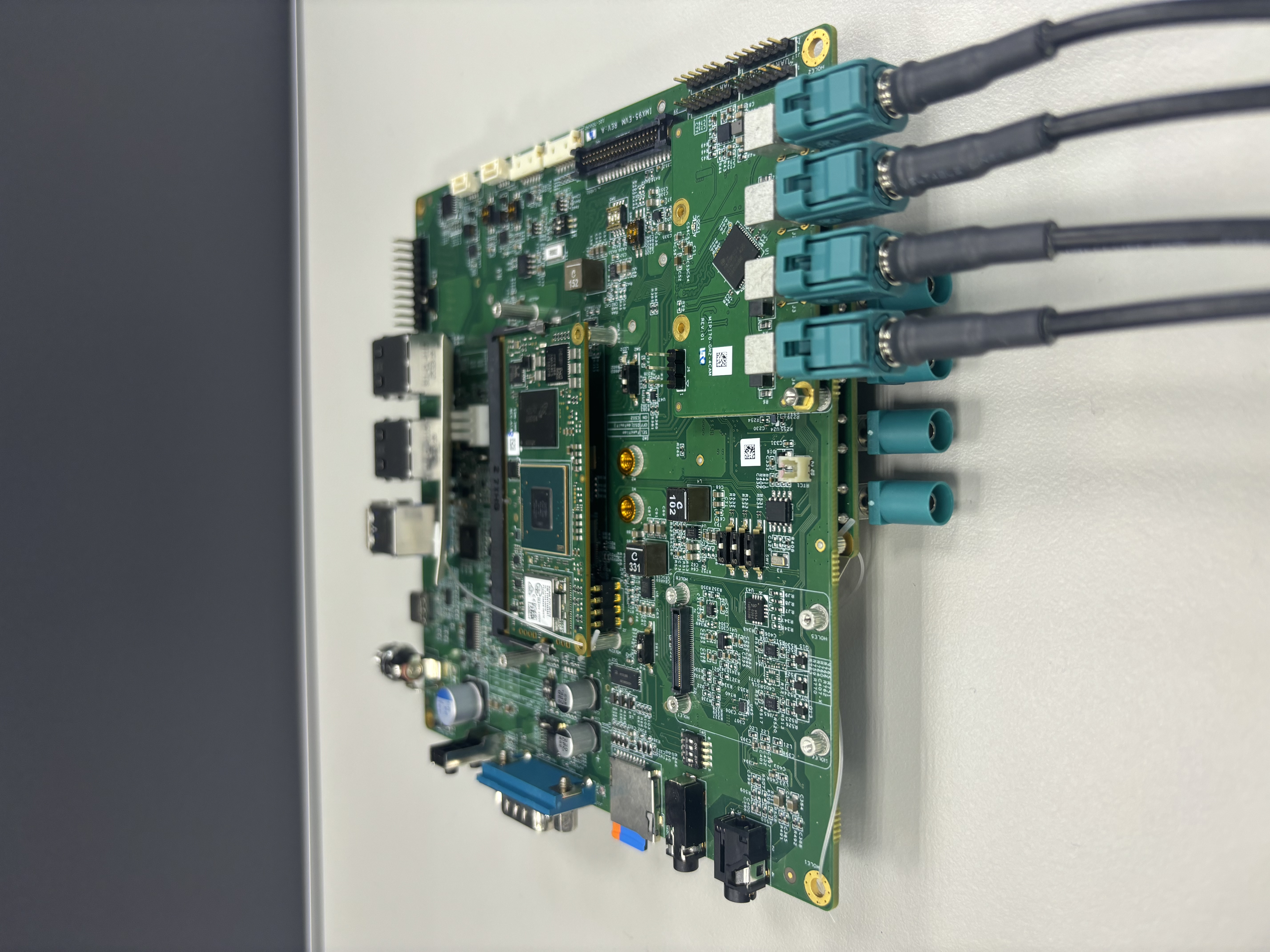 | CSI2 P3P2P1P0 CSI1 P0P1P2P3 | |
8 cameras (both ports) VxRoute_iMX95_GMSL_CSI1_CSI2.yaml | 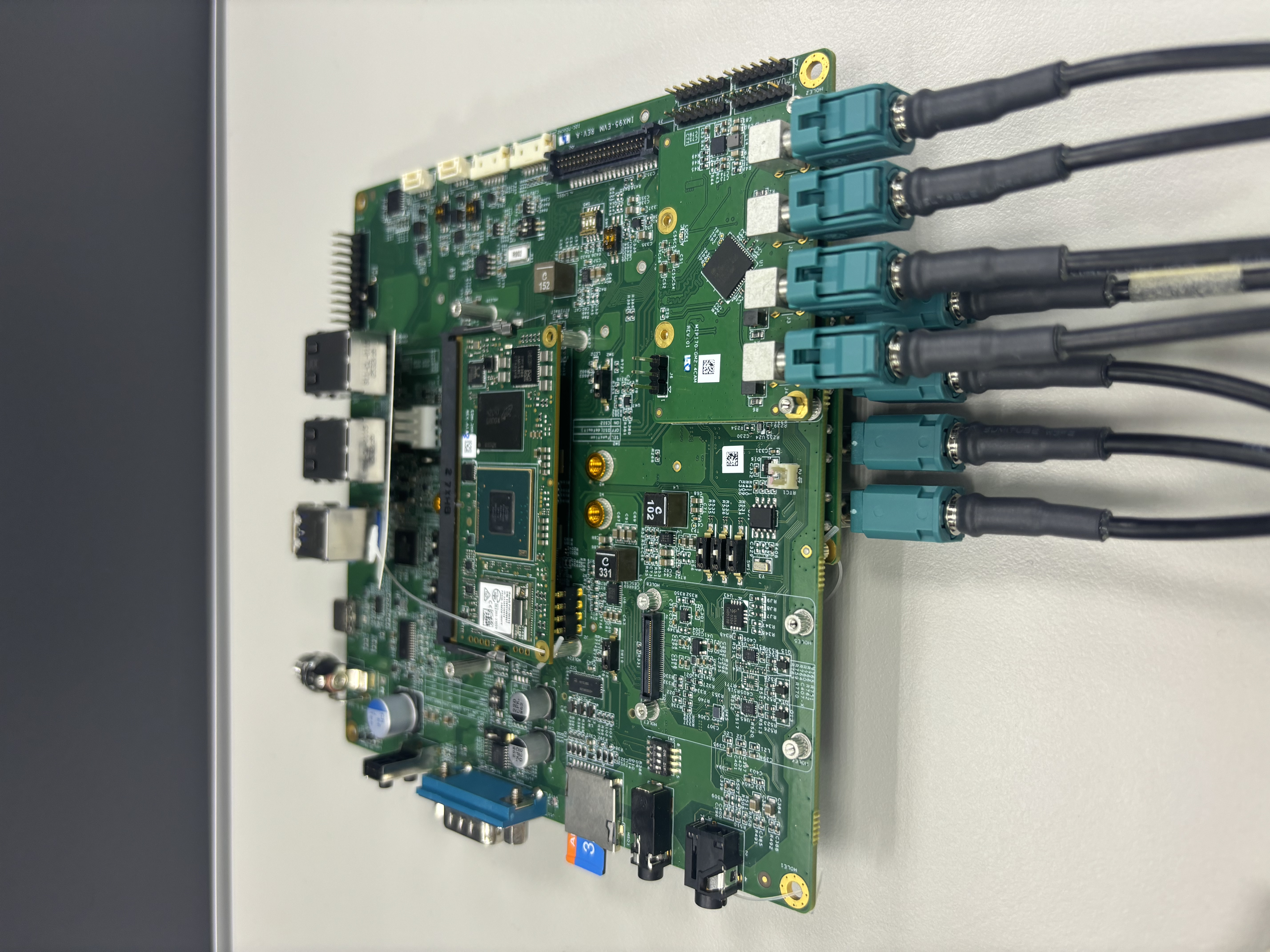 | CSI2 P3P2P1P0 CSI1 P0P1P2P3 |
Advanced: Port Mapping and Collision Prevention (Click to expand)
Collision Risk: Crossbar Output Config
The Crossbar sits at the end of the pipeline, collecting streams from the Formatters and distributing them to the ISIs.
- Pipeline A (Formatter@20) connects to Crossbar Input Pad 2.
- Pipeline B (Formatter@120) connects to Crossbar Input Pad 3.
A collision occurs if you try to route both input pipelines to the same output destination (ISI) simultaneously.
- Correct: Pipeline A -> route to ISI.0 (Pad 5) | Pipeline B -> route to ISI.1 (Pad 9).
- Collision: Pipeline A -> ISI.0 | Pipeline B -> ISI.0.
Physical Port Mapping Table
Use the table below to ensure you are targeting the correct devices in your YAML file.
| Physical Port | YAML Device Name | Connected Pipeline |
|---|---|---|
| CSI1 | csidev-4ad30000.csi | Pipeline A (via Formatter@20) |
| CSI2 | csidev-4ad40000.csi | Pipeline B (via Formatter@120) |
Crossbar Pad Reference
The Crossbar is the core routing component. Understanding the pad layout is critical for avoiding collisions.
| Pad Type | Pad Number | Connected Device | Pipeline |
|---|---|---|---|
| Input | Pad 2 | Formatter@20 | Pipeline A (CSI1) |
| Input | Pad 3 | Formatter@120 | Pipeline B (CSI2) |
| Output | Pad 5 | mxc_isi.0 | ISI Channel 0 |
| Output | Pad 6 | mxc_isi.1 | ISI Channel 1 |
| Output | Pad 7 | mxc_isi.2 | ISI Channel 2 |
| Output | Pad 8 | mxc_isi.3 | ISI Channel 3 |
| Output | Pad 9 | mxc_isi.4 | ISI Channel 4 |
| Output | Pad 10 | mxc_isi.5 | ISI Channel 5 |
| Output | Pad 11 | mxc_isi.6 | ISI Channel 6 |
| Output | Pad 12 | mxc_isi.7 | ISI Channel 7 |
- Pipeline A cameras (CSI1) typically route from Pad 2 → Pads 5-8 (ISI.0-3)
- Pipeline B cameras (CSI2) typically route from Pad 3 → Pads 9-12 (ISI.4-7)