PICO-PI-IMX8M
The PICO-PI-IMX8M development kit comprises a PICO-PI-8M baseboard and an PICO-IMX8M System-on-Module. The PICO-PI-8M Baseboard is a printed circuit board assembly (PCBA) designed to be compatible with TechNexion's PICO family of System-on-Modules (SoMs). It supports various external connectors and peripheral devices.
Overview
| Feature | Description |
|---|---|
| Displays | HDMI + MIPI-DSI (4x-lanes) + touchscreen |
| USB Type C | 1x USB 2.0 OTG |
| USB Type A | 1x USB 2.0 Host |
| Network | 1x 10/100/1000 Ethernet RJ45 jack |
| Camera | 2x MIPI-CSI camera connectors (33-pin FPC) |
| Audio | via audio expansion header |
| I/O Expansion | 1x 40-pin header (similar to Raspberry Pi) |
| Console | USB-UART console device on-board |
| Power Supply | 5 VDC via USB Type C |
The SD card slot on the PICO-PI-8M baseboard may be populated, but is not active when the board is populated with PICO-IMX8M. The NXP i.MX8M SOC has 2 ESDHC ports. One of them is used for connecting the SOC to the e.MMC on the module, and the other is the main data interface to the WLAN radio.
Board Pictures
| Top view, with PICO-IMX8M System-on-Module assembled |
|---|
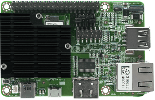 |
| Bottom view |
|---|
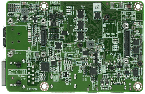 |
| With 720x1280 MIPI-DSI touchpanel kit (Panel sold separately) |
|---|
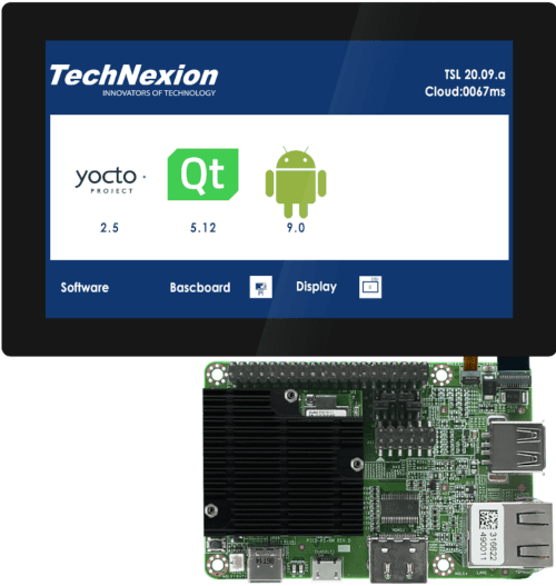 |
Kit Contents
The PICO-PI-IMX8M kit contains the following:
- PICO-PI-8M baseboard
- PICO-IMX8M module, preassembled with heatsink
- Wireless antenna (PCB type)
- MicroUSB cable (for serial console)
- USB Type A to Type C cable (for power and programming)
Getting Started
Connecting the Serial Console Cable
The PICO-PI-8M kits are supplied with a microUSB cable. To interact with the main Cortex-A series processor console port, this cable must be connected to microUSB connector on the PICO-PI-8M baseboard.
On the PICO-PI-8M baseboard, the USB-UART bridge IS is powered by the board, not by the USB host interface. When the board power is cycled, or if the SOM is reset, the USB serial port will disconnect and then reconnect.
Board Power
The PICO-PI-8M baseboard can be powered by the USB type C connector (5V).
Install Demo Software Images
When your kit arrives, it will be preprogrammed with an image that will assist you in loading software onto the board for the first time. This image is known as the TechNexion Software Loader (or TSL).
The TSL connects the kit to an internet-connected network via the Ethernet port. It operates as a graphical user interface application and functions optimally when used with an attached display, such as the 5" MIPI-DSI touchpanel kit, which is available for purchase when you order the PICO-PI-IMX8M.
The TSL will guide you through a series of screens, enabling you to choose the type of image (Yocto, Debian, or Android) and the storage location (e.g. eMMC, SD card).
Additional Demo Images
If you want to download additional demo images, you can easily do this by navigating your browser to our download server. We usually update these 2-3 times a year as we release updated BSPs.
Download Additional PICO-IMX8M Demo Images
Flashing e.MMC
During development or initial manufacturing, you may want to flash the entire e.MMC. Or, you way want to recover a 'bricked' unit (one that will not boot). To do this, you can follow our step-by-step tutorial showing how to use the uuu tool here:
If the board boots, and you have access to a serial console, you may want to use U-boot's ums command to load software to the e.MMC:
Using U-boot's 'ums' command to flash e.MMC
Recovery to Factory Settings
It may be necessary or desireable to recover the unit to factory settings. For example, you may want to use the Technexion Software Loader to download and install a different demo image to the board.
The process for doing this is identical to flashing a regular Linux image to your board, except that you would need to download the TechNexion Software Loader (TSL) image instead.
| Download Software Loader Image |
|---|
| PICO-PI-IMX8M - HDMI display |
| PICO-PI-IMX8M - MIPI-DSI display |
Boot Media and Boot Mode Selection
PICO-IMX8M boots into 2 modes: onboard e.MMC boot, and serial download mode. Serial download mode allows images to be loaded over USB. These settings are controlled using boot configuration jumpers. See the table below.
Note the default boot media is EMMC. On the module, we configure boot configuration signals to boot from the default media without needing to be pulled high or low on the baseboard. You can either leave the jumpers as set here, or remove them.
Boot from e.mmc
| mode | jumper configuration |
|---|---|
| boot from e.mmc | 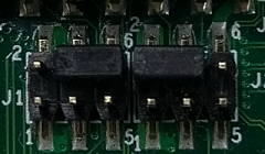 |
Boot into serial download mode
| mode | jumper configuration |
|---|---|
| serial download mode | 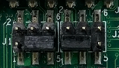 |
Documentation
Refer to the SoM product page’s Documentation section for details on the development kit. It includes schematics for all baseboards and PCB files.
Support
Having trouble? Please check out our support page for available support options.