Intel Panther Lake CRB GMSL2 Cameras
Introduction
This article explains how to enable TechNexion VLS-GM2 Cameras on the Intel Panther Lake CRB platform. It covers the required BIOS, OS, driver, and camera preview configuration for VLS-GM2 Cameras on Intel Panther Lake CRB.
Supported Camera Modules
| Camera Series | Products |
|---|---|
| VLS-GM2 | VLS-GM2-AR0144 VLS-GM2-AR0145 VLS-GM2-AR0234 VLS-GM2-AR0235 VLS-GM2-AR0246 VLS-GM2-AR0521 VLS-GM2-AR0522 VLS-GM2-AR0544 VLS-GM2-AR0821 VLS-GM2-AR0822 VLS-GM2-AR0830 VLS-GM2-AR1335 VLS-GM2-AR2020 |
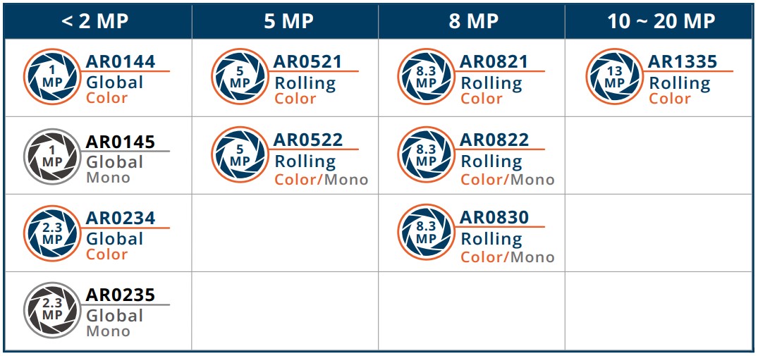
More Camera Products Details...
Software Installation Instructions
BIOS Configurations
Configure the camera settings in the BIOS first. Follow the steps below.
-
Power on the Intel Panther Lake CRB device and press the
F2key to enter the BIOS setup. -
Use the arrow keys to navigate to
Intel Advanced Menu -> Power & performance -> CPU - Power Management Controland setC statesto Disabled. -
Use the arrow keys to navigate to
Intel Advanced Menu -> System Agent (SA) Configuration -> MIPI Camera Configurationand setCVF/CVS Supportto Disabled. -
Use the arrow keys to navigate to
Intel Advanced Menu -> System Agent (SA) Configuration -> MIPI Camera Configuration. -
Enable
Camera 1andCamera 2to showLink options. -
Set up the
Camera 1andCamera 2link options according to the tables below.
Camera 1 Link Options
| Options | Parameter |
|---|---|
| Sensor Model | <User Custom> |
| Custom HID | VLSGM296 |
| Lanes Clock division | <4 4 2 2> |
| CRD Version | <CRD-D> |
| GPIO control | <Control Logic 1> |
| Camera position | <back> |
| Flash Support | <Driver default> |
| Privacy LED | <Driver default> |
| Rotation | <180> |
| PPR Value | [2] |
| PPR Unit | [4] |
| Camera module name | tevs |
| MIPI port | [0] |
| LaneUsed | <x4> |
| MCLK | [19200000] |
| EEPROM Type | <ROM_NONE> |
| VCM Type | <VCM_NONE> |
| Number of I2C Components | [3] |
| I2C Channel | <I2C1> |
| Device 0 | |
| I2C Address | [0x27] |
| Device Type | <Sensor> |
| Device 1 | |
| I2C Address | [0x44] |
| Device Type | <Sensor> |
| Device 2 | |
| I2C Address | [0x54] |
| Device Type | <Sensor> |
| Customize Device ID List | |
| Customize Device1 ID Number | [17] |
| Customize Device1 ID Number | [18] |
| Customize Device1 ID Number | [19] |
| Flash Driver Selection | <Disabled> |
Camera 2 Link Options
| Options | Parameter |
|---|---|
| Sensor Model | <User Custom> |
| Custom HID | VLSGM296 |
| Lanes Clock division | <4 4 2 2> |
| CRD Version | <CRD-D> |
| GPIO control | <Control Logic 2> |
| Camera position | <back> |
| Flash Support | <Driver default> |
| Privacy LED | <Driver default> |
| Rotation | <0> |
| Voltage Rail | <3 voltage rail> |
| PPR Value | [2] |
| PPR Unit | [4] |
| Camera module name | tevs |
| MIPI port | [2] |
| LaneUsed | <x4> |
| MCLK | [19200000] |
| EEPROM Type | <ROM_NONE> |
| VCM Type | <VCM_NONE> |
| Number of I2C Components | [3] |
| I2C Channel | <I2C2> |
| Device 0 | |
| I2C Address | [0x27] |
| Device Type | <Sensor> |
| Device 1 | |
| I2C Address | [0x44] |
| Device Type | <Sensor> |
| Device 2 | |
| I2C Address | [0x54] |
| Device Type | <Sensor> |
| Customize Device ID List | |
| Customize Device1 ID Number | [17] |
| Customize Device1 ID Number | [18] |
| Customize Device1 ID Number | [19] |
| Flash Driver Selection | <Disabled> |
OS Configurations
Install Ubuntu 24.04. You can download it from the following website.
Download latest LTS Ubuntu 24.04
Camera Drivers Installation
After installing and setting up Ubuntu 24.04, please follow the steps below to complete the Camera Driver installation.
- Download the driver packages to the device. Download DEB Packages You can use the following command to download the packages:
wget https://download.technexion.com/demo_software/EVK/Intel/PTL/release/tn-camera-ptl.tar.gz
- Next, extract the file and run the
install.shscript to install the camera driver packages.
tar xf tn-camera-ptl.tar.gz && sudo ./tn-camera-ptl/install.sh
- After installation is complete, reboot the device and verify the installed kernel version.
$ uname -r
6.17.0-tn-ptl-260128t080735z
Enable Cameras
Use the test script to enable cameras.
vlsgm2-1 through vlsgm2-4 are assigned by the deserializer to port 0. vlsgm2-5 through vlsgm2-8 are assigned by the deserializer to port 2.
For example:
- Enable a single sensor:
launch_video_pipeline_ptl.sh vlsgm2-1 1280x720 UYVY
launch_video_pipeline_ptl.sh vlsgm2-5 1280x720 UYVY
- Enable all sensors on one port:
launch_video_pipeline_ptl.sh MULTICAMx4-CSI0 1920x1080 UYVY
launch_video_pipeline_ptl.sh MULTICAMx4-CSI2 1920x1080 UYVY
- Enable all sensors on both ports:
launch_video_pipeline_ptl.sh MULTICAMx8 640x480 UYVY